Design
Purpose
The Design Document - Part I Architecture describes the software architecture and how the requirements are mapped into the design. This document will be a combination of diagrams and text that describes what the diagrams are showing.
Components
Client

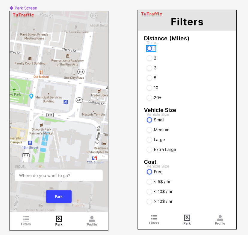
Figure 1 - Mobile App Wireframe
Figure 1 shows a mockup wireframe of the TuTraffic mobile application.
- This is an android application that will require the use of 3 main pages with adjacent xml files and adapters for each view used.
- The client will be connected to the server via built in functionality within android studio and google cloud. These classes are autogenerated by android studio and are shown as RegisterActivity and DeviceInfoEndpoint respectively.
Figure 2.1 - Frontend Application Class Diagram
Figure 2.1 shows the class diagram of TuTraffic's application and all the components that make up the frontend.
Server
The server will be hosted in Google Cloud with containers for the Customer database, and Parking database.
Figure 2.2 - Backend Flowchart
Figure 2.2 illustrates the flow of components that make up the backend, highlighting the communcation between the server and the databases.
Database
- Uses Firebase to save customer information, location and availbe parking spots.
- Customer table contains CustomerId as the primary key, customer's email and password, and two foreign keys LocationId and ParkingSpotId.
- Path from CustomerInfo to Location table has LocationId as the primary key and also the user's longitude and latitude.
- Path from CustomerInfo to ParkingSpot, which had spotLocationId as the primary key and also the parkings spot's longitude, latitude, price and availability.
Figure 2.3 - Database Class Diagram
Figure 2.3 shows the class diagram of the different data fields stored in the TuTraffic database.
Raspberry Pi
- A camera is attached to the Raspberry Pi that sends it images. The Pi runs code on itself to process the images then sends the gathered data to the server.
- No images are sent to the server, only the data detected from them.
Figure 2.4 - Raspberry Pi Class Diagram
Figure 2.4 illustrates the class diagram of the code run on the Raspberry Pi after an image is sent to it from its camera.
Sequence Diagrams
Use Case #1: A user knows their destination and wants to find a spot in its general vicinity.
Use Case 1 Description
- Upon opening the TuTraffic application, the user opens the parking options page, a page that acts as the settings for the users parking preferences and needs.
- In the range subsection of the parking options page, the user can adjust the range of how far they are willing to park in the area surrounding from their destination.
- The user clicks save and exits the parking options page to return to the home screen.
- On the home screen, the user can click the search button to enter the address of their destination.
- The TuTraffic application displays a map of the detected spots in the saved range of the destination to the user's device.
Use Case #2: A user wants to update their personal parking options to reflect how much they are willing to pay per hour for street parking.
Use Case 2 Description
- The user logs into their account on the TuTraffic application.
- The user opens parking options, where their saved preferences are stored.
- In the parking type subsection of the parking options page, the user removes parking garages and paid lots from their preferred list.
- In the per hour subsection of the parking options page, the user edits their accepted hourly price range, reflecting how much they are willing to pay per hour.
- The user clicks save and exits the parking options page to return to the home screen, where only street parking that is less than or equal to their budget will appear on the map.
Use Case #3: A user wants to indicate their car size as to only be shown parking spaces that are likely to fit their car.
Use Case 3 Description
- A logged in user opens the parking options page.
- In the car size subsection of the parking options page, the user selects the option that best reflects the size of their car from a dropdown menu: small, medium, or large.
- The user clicks save.
- The TuTraffic application sends a message to the server to communicate the unique size need.
- The server requests this information of parking spots of a particular size to the database.
- The database, which continuously receives data from the Raspberry Pi node of parking spots and their location and size, sends the appropriate information back to the server.
- Now, when the user searches for spots, only parking spots that have been detected to likely fit at least their size will appear.
Use Case #4: A user wants be directed to a parking spot after selecting it.
Use Case 4 Description
- After opening the TuTraffic application, the user clicks the search button to find parking spots.
- The user enters their destination's address.
- The TuTraffic application displays the detected spots to the user's device.
- After browsing, the user selects on a parking spot and clicks the route button.
- The Google Maps API is loaded to direct the user to their destination.
Algorithms
Computer Vision
The Raspberry Pi nodes utilized for this product are equipped with cameras that will take photos at fixed intervals in order to be sending up-to-date data to the server. To ensure real-time processing so users will not be presented with inaccurate information, the Raspberry Pi will take and process multiple images a minute. When a Raspberry Pi node takes a photo, the photo will be edited and processed through a computer vision algorithm hosted on the Raspberry Pi itself. Computer vision is a subfield of machine learning, meant to view images and replicate the human thought process to make a decision based on what it "sees".
Currently, the computer vision aspect of TuTraffic is being developed with the detection algorithm YOLO. YOLO is a relatively fast object detection algorithm as it utilizes a one-stage detector strategy - this means as opposed to other much slower algorithms, YOLO looks at an image only once and goes through its entire network one time to determine if objects it has been trained to detect are present. YOLO is run on OpenCV, an open source computer vision/machine learning software library. One of the classes in YOLO's detectable objects list are cars - car detection will be a necessary tool in detecting parking spots on streets.
TuTraffic detects both street parking and parking in traditional parking lots. YOLO's car detection is the biggest component of street parking, while OpenCV's built in line detection is the biggest component for parking spots in a parking lot. OpenCV has a fast line detection algorithm built into its library and does not require the use of any additional object detection algorithms. YOLO's car detection and OpenCV's line detection will work together to detect parking spots in both environments.

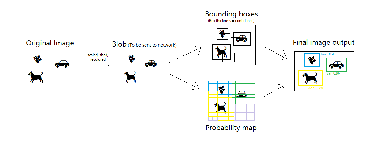
Figure 3.1 - YOLO diagram
Figure 3.1 shows the process an image goes through and its output when ran through the YOLO object detection algorithm supported by OpenCV. The original image is first transformed into a blob format to be read by the network. YOLO then completes two steps - one surrounding the blob in boxes of different thickness to indicate confidence of an object being present, and the other adding a colored probability map over the image to indicate the objects the algorithm believes exists in those locations. The bounding boxes and probability map are combined to create the final image, boxes surrounding the detected objects with their label & probability.
State Diagrams
Figure 4.1 - Client State Diagram
Figure 4.1 shows the state diagram of the frontend application, describing the different behaviors of the TuTraffic application.
The TuTraffic client application experiences multiple states throughout its usage. As depicted in the figure above, its first state is Searching: in this state, the client displays a list of nearby parking spaces, which may be initially empty. The client enters the Viewing state after the user selects a parking location; they can return to the Searching state to view the other locations, or enter the Navigation state. In either the Searching or Viewing State, the client submits requests to the server, such as parking status updates or reservations, in the Requesting state before returning to the previous state. In the Navigation state, the client connects to a third party navigation service and receives real-time driving assistance to help them reach their selected parking location. After the client reaches their destination or ceases navigation, the application returns to the Viewing state.
Figure 4.2 - Server State Diagram
Figure 4.2 shows the state diagram of the backend server, exhibiting the different modes the server may be acting in.
The figure above illustrates the server states of the TuTraffic system. The server starts in the Waiting state; it is idle while there are no jobs to complete. When it receives a request from a client or node, the server proceeds to the Handling state, in which it comprehends the request. Then, the server enters a Reading or Writing state to handle the reading or writing operations, respectively, that are necessary to fulfill the request. For example, a search query is primarily a reading operation, while a parking reservation request is primarily a writing operation. Finally, the server formulates a response, delivers the message in the Replying state, and returns to the Waiting state before the next job.
Figure 4.3 - Raspberry Pi Node State Diagram
Figure 4.3 shows the state diagram of the Raspberry Pi node as it cycles through different behaviors.
Each Raspberry Pi node in the TuTraffic system begins in the Waiting state, as shown in the above state diagram. The node exits this Waiting state on a regular schedule or upon request, then enters the Capturing state, during which it records an image. The node proceeds to the Processing state, in which computer vision is used to produce a parking location update message. This update is pushed to the server during the Sending state, then the node resumes the Waiting state.
Database
Figure 5.1 - Database Entity-Relation Diagram
Figure 5.1 shows the relationship between the different entities of TuTraffic's database.
Table Design
- Customer Table: This table contain customer information including, email and password. The primary key is customerId. Contains 2 foreign keys locationId and spotID
- Location Table: This table updates in realtime with users longitude and latitude. The primary key is locationId.
- ParkingSpot Table: This table contains the parking spots location, availability and longitude and latitude. Primary key is the spotId